
描述
产品简要说明
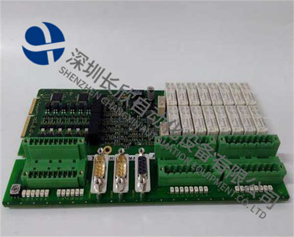
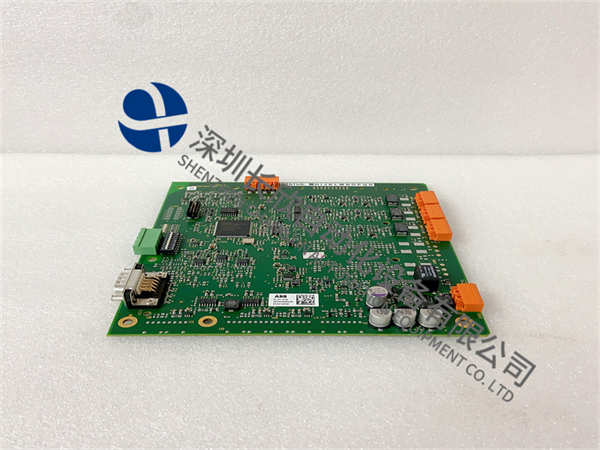
ALSTOM MX3EG1A.72是阿尔斯通(Alstom)专为电力系统并网设计的高精度自动同步控制器,核心特性包括:
双模式并网控制:支持带电母线/不带电母线自动切换(响应时间≤200ms)
多参数校准:
最大电压偏差±5%(母线电压/额定电压)
最大频率偏差±2Hz(额定频率/母线频率)
智能诊断系统:
记录8次事件日志(含时间、电压/频率值、相差等)
实时监测输出继电器状态(18个逻辑状态采样)
多协议通信:
LONWORKS总线(远程监控)
MODBUS RS485(本地配置)
双设置组管理:支持主/备参数组快速切换
产品详细说明
1.核心控制逻辑
并网顺序起动
预同步流程:
检测母线电压(Ubn)与发电机电压(Ugn)有效值(Ubn倍数表示)
校验频率差(Δf)与相差(Δφ)
启动调压器(最低发电机电压阈值:Ugn×0.7)
触发并网命令(最大尝试次数可设)
调压器与频率稳定器
电压控制阈值:
最大电压差:Ubn±10%
最低发电机电压:Ugn×0.7
频率稳定参数:
最大频率偏差:±2Hz(母线/发电机)
最大频率差:±0.5Hz
备用母线模式
三种工作状态:
OFF:仅主母线控制
ON:备用母线实时同步
ON-CHECK:备用母线状态预检(相差校准)
2.智能运维系统
诊断与记录:
事件日志:存储最后8次并网事件(含时间、电压/频率值、相差、尝试次数)
计数器:累计并网成功/失败次数
RCE记录:32次状态变化(需PC或网络读取)
示波扰动分析:
2.5秒瞬时值记录(每周期12次采样)
包含电压/频率波形与数字输入状态
3.人机交互设计
LCD菜单结构:
主读数菜单:实时显示电压/频率值、相差、输出继电器状态
主设置菜单:
参数组切换(主/备)
语言选择(中/英/西)
日期/时间校准
测试菜单:
继电器自检
通信协议模拟
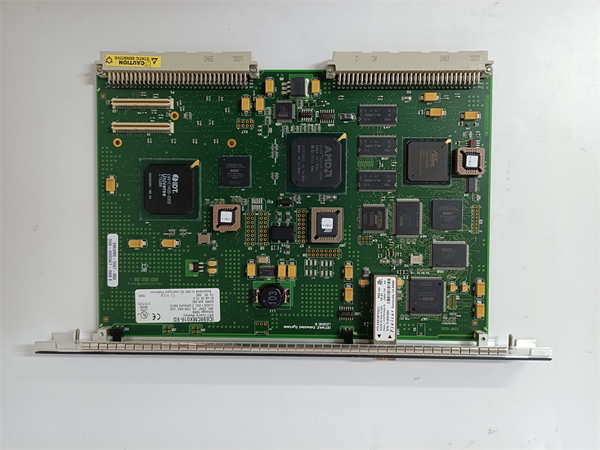
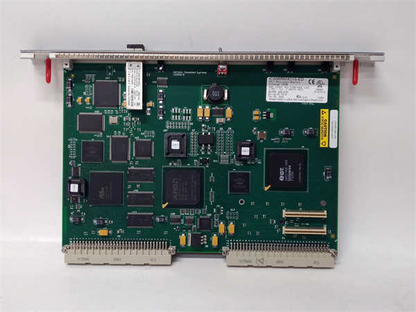
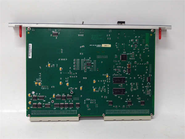
DS200KLDBG1ABC
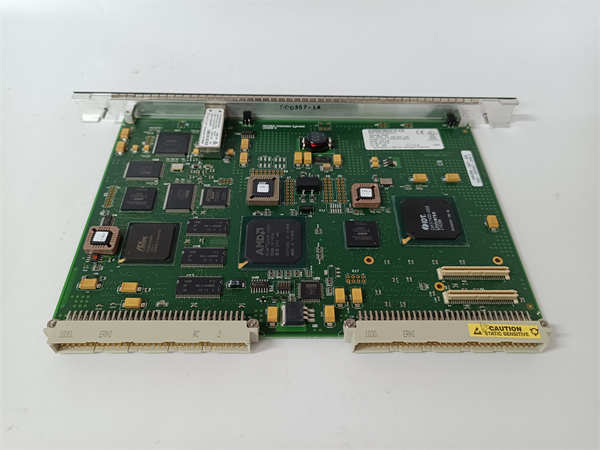
DS200KLDBG1ABC
Product brief description
ALSTOM MX3EG1A.72 is a high-precision automatic synchronization controller designed by Alstom for grid connection to power systems.The core features include:
Dual mode grid-connected control:supports automatic switching of live bus/unrelease bus(response time≤200ms)
Multi-parameter calibration:
Maximum voltage deviation±5%(bus voltage/rated voltage)
Maximum frequency deviation±2Hz(rated frequency/bus frequency)
Intelligent diagnostic system:
Record 8 event logs(including time,voltage/frequency value,phase difference,etc.)
Real-time monitoring of output relay status(18 logical state samples)
Multi-protocol communication:
LONWORKS bus(remote monitoring)
MODBUS RS485(local configuration)
Dual-set group management:supports quick switching of primary/secure parameter groups
Product details
1.Core control logic
Start the grid connection sequence
Pre-synchronization process:
Detect bus voltage(Ubn)and generator voltage(Ugn)effective value(denoted by Ubn multiple)
Verification frequency difference(Δf)and phase difference(Δφ)
Start the voltage regulator(minimum generator voltage threshold:Ugn×0.7)
Trigger the grid connection command(maximum number of attempts can be set)
Voltage regulator and frequency stabilizer
Voltage control threshold:
Maximum voltage difference:Ubn±10%
Minimum generator voltage:Ugn×0.7
Frequency stability parameters:
Maximum frequency deviation:±2Hz(busbar/generator)
Maximum frequency difference:±0.5Hz
Alternate bus mode
Three working states:
OFF:Only the master busbar control
ON:Real-time synchronization of backup bus
ON-CHECK:backup bus status pre-check(phase difference calibration)
2.Intelligent operation and maintenance system
Diagnosis and Recording:
Event log:Store the last 8 grid-connected events(including time,voltage/frequency value,phase difference,number of attempts)
Counter:cumulative number of successful/failed connections
RCE record:32 state changes(requires PC or network reading)
Oscillo-perturbation analysis:
2.5 seconds instantaneous value record(12 samples per cycle)
Includes voltage/frequency waveform and digital input state
3.Human-computer interaction design
LCD menu structure:
Main reading menu:Real-time display of voltage/frequency value,phase difference,output relay status
Main Settings Menu:
Parameter group switching(main/standby)
Language selection(Chinese/English/Western)
Date/time calibration
Test menu:
Relay self-test
Communication protocol simulation