
描述
1.产品定位与核心功能
类型:
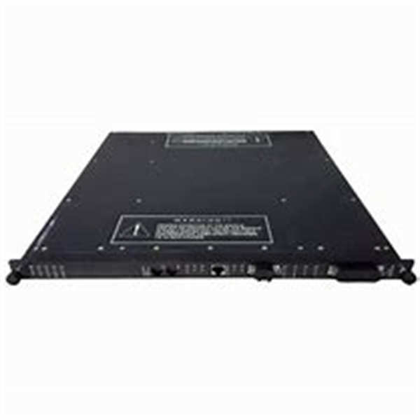
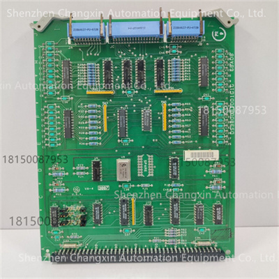
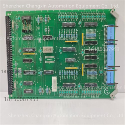
数字量输入/输出(DIO)控制模块,属于GE DS3800系列中用于离散信号处理的关键组件,专注于高可靠性数字信号采集与控制指令输出。
核心用途:
输入功能:
采集燃气轮机现场设备的开关量信号(如阀门状态、断路器分合闸、安全联锁触点等)。
支持干接点(无源触点)或湿接点(有源信号,如24V DC)输入,兼容多种传感器类型。
输出功能:
驱动电磁阀、继电器、指示灯等执行器,实现控制逻辑的物理动作(如燃料阀开启、报警触发)。
输出通道具备短路保护和过载能力,确保系统安全。
系统角色:
作为Mark II/IV控制器与现场设备之间的数字信号接口,承担安全关键信号的隔离与转换。
2.关键技术参数
输入通道特性
通道数量:
典型配置为16路数字输入(具体以模块标牌为准),支持分组配置(如8路干接点+8路湿接点)。
信号类型:
干接点:无源触点(需外部供电,如24V DC由模块内部提供)。
湿接点:有源信号(电压范围12-48V DC,兼容TTL/CMOS电平)。
电气参数:
输入阻抗:≥10kΩ(湿接点模式)。
隔离电压:输入与系统电源间隔离电压≥2500V AC(符合IEC 60664-1标准)。
响应时间:≤5ms(从信号变化到控制器读取)。
输出通道特性
通道数量:
典型配置为8路数字输出(继电器触点或固态开关输出)。
输出类型:
继电器触点:
触点容量:24V DC/5A(电阻性负载)或125V AC/3A(感性负载)。
机械寿命:≥10^6次操作。
固态开关(可选):
最大负载电流:2A(持续),峰值电流5A(10ms)。
响应时间:≤1ms(从控制器指令到输出动作)。
保护功能:
过载保护:输出短路时自动限流,避免模块损坏。
反极性保护:防止电源接反导致的元件损伤。
通信与接口
内部通信:
通过GE专用背板总线(并行或高速串行接口)与Mark II/IV控制器交换数据。
数据刷新率:≥100Hz(确保实时性)。
外部接口:
接线端子:采用可拆卸式端子排(如Phoenix Contact或WAGO型号),支持快速维护。
标识:每个通道标注功能说明(如“VALVE_OPEN”“TRIP_SIGNAL”),便于现场调试。
1.Product Positioning and Core Functions
Type:
This digital input/output(DIO)control module is a key component for discrete signal processing in the GE DS3800 series,focusing on high-reliability digital signal acquisition and control command output.
Core Application:
Input Function:
Acquires digital signals from gas turbine field devices(such as valve status,circuit breaker opening/closing,safety interlock contacts,etc.).
Supports dry contact(passive contacts)or wet contact(active signals,such as 24V DC)inputs and is compatible with a variety of sensor types.
Output Function:
Drives actuators such as solenoid valves,relays,and indicator lights to implement physical actions in control logic(such as opening a fuel valve or triggering an alarm).
Output channels feature short-circuit protection and overload capability to ensure system safety.
System Role:
Serves as the digital signal interface between the Mark II/IV controller and field devices,isolating and converting safety-critical signals.2.Key Technical Parameters
Input Channel Characteristics
Number of Channels:
Typical configuration:16 digital inputs(see module label for details).Group configuration is supported(e.g.,8 dry contacts+8 wet contacts).
Signal Type:
Dry Contact:Passive contact(requires external power supply,e.g.,24V DC supplied internally by the module).
Wet Contact:Active signal(voltage range:12-48V DC,compatible with TTL/CMOS levels).
Electrical Parameters:
Input Impedance:≥10kΩ(wet contact mode).
Isolation Voltage:≥2500V AC between input and system power supply(compliant with IEC 60664-1).
Response Time:≤5ms(from signal change to controller readout).
Output Channel Characteristics
Number of Channels:
Typical configuration:8 digital outputs(relay contacts or solid-state switch outputs).Output Type:
Relay Contacts:
Contact Rating:24V DC/5A(resistive load)or 125V AC/3A(inductive load).
Mechanical Life:≥10^6 operations.
Solid-State Switch(Optional):
Maximum Load Current:2A(Continuous),Peak Current:5A(10ms).
Response Time:≤1ms(from controller command to output action).
Protection Functions:
Overload Protection:Automatically limits current when the output is short-circuited,preventing module damage.
Reverse Polarity Protection:Prevents component damage caused by reverse power connection.
Communications and Interfaces:
Internal Communication:
Data is exchanged with the Mark II/IV controller via a GE-specific backplane bus(parallel or high-speed serial interface).
Data Refresh Rate:≥100Hz(ensuring real-time performance).
External Interfaces:
Terminal Blocks:Utilize removable terminal blocks(such as Phoenix Contact or WAGO models)for quick maintenance.Label:Each channel is labeled with its function description(such as”VALVE_OPEN”and”TRIP_SIGNAL”)to facilitate on-site debugging.
ABB Model: GBU72 3BHE055094R0002 Model: 3BHE055094R0002 GBU72 Model: GBU72 Model: 3BHE055094R0002 Model: 3BHE031197R0001 Model: 3BHB030310R0001 Model: 73BHE055094R0002 GBU72 Model: 73BHE055094R0002 Model: GBU72 Model: ABB PCS6000 PRODUCT FAMLIY ABB 5SHY4045L0006 3BHB030310R0001 3BHE039203R0101 GVC736CE101