
描述
一、核心特性
高速光纤通信
带宽:支持40 Gbps全双工数据传输(每方向20 Gbps),满足大规模数据实时传输需求。
延迟:典型往返延迟<1μs,确保远程控制响应速度接近本地操作。
距离:支持最长300米多模光纤连接(OM4光纤),或10公里单模光纤连接(OS2光纤)。
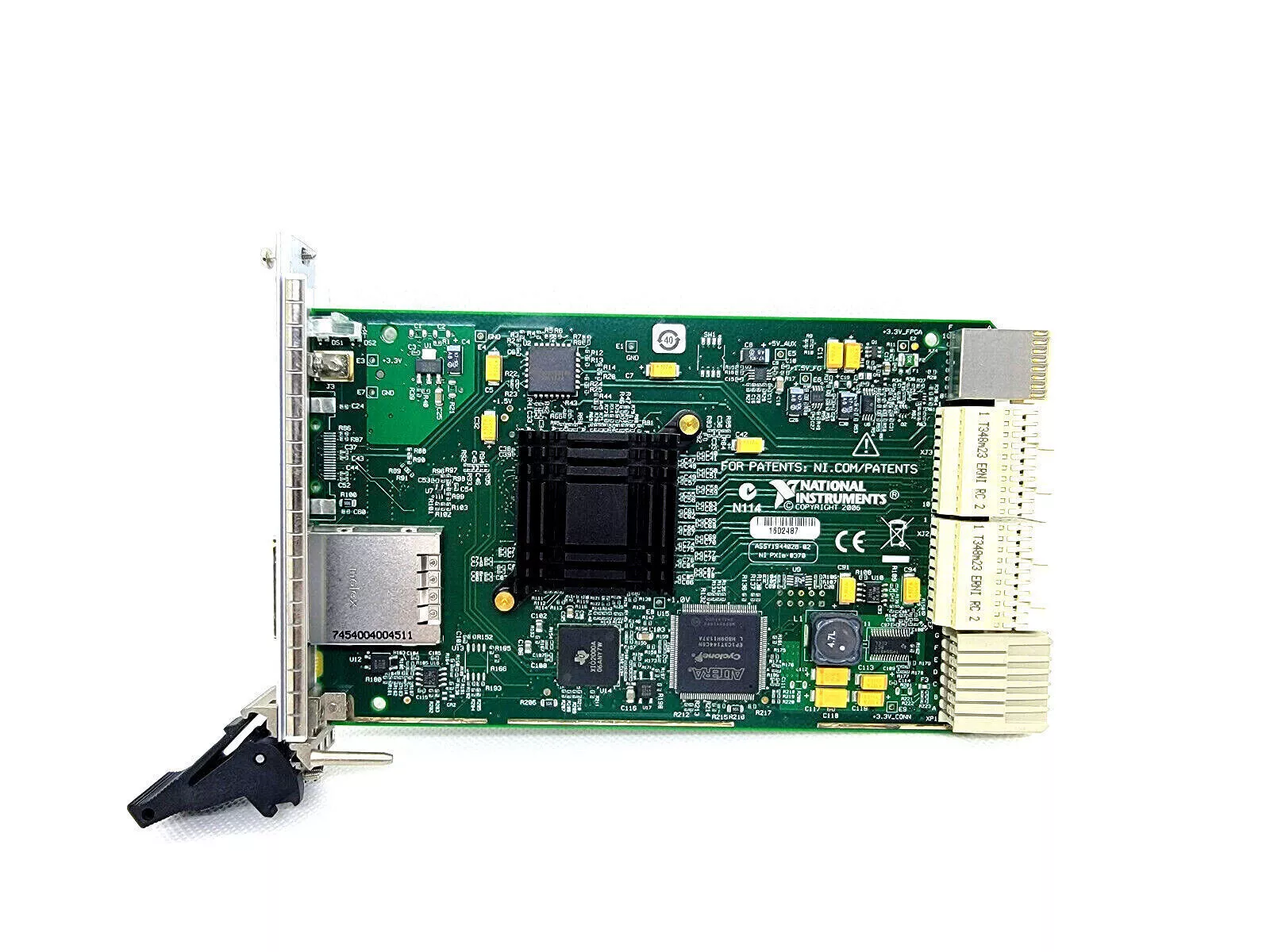
无缝PXI Express集成
兼容性:完全兼容PXI Express标准,支持与NI PXIe-1085、PXIe-1082等机箱无缝连接。
触发同步:通过光纤链路传输PXI触发信号,实现远程机箱与主控制器纳秒级同步(<10 ns抖动)。
时钟同步:支持IEEE 1588时间同步协议,确保多机箱时间一致性(精度<100 ns)。
灵活的系统扩展
级联能力:支持多级级联(如主控制器→PXIe-8370→另一PXIe-8370),构建分布式测试网络。
混合拓扑:支持星型、链型或树型拓扑,适应不同测试场景需求。
热插拔:支持机箱运行时插拔,简化系统维护与升级。
高可靠性设计
冗余电源:支持双电源输入,提高系统可用性。
工业级温度范围:工作温度0°C至55°C,存储温度-40°C至70°C,适应恶劣环境。
ESD保护:符合IEC 61000-4-2标准,防止静电损坏。
二、技术规格
参数规格
接口类型1×QSFP+光纤接口(支持40 Gbps全双工)
光纤类型多模光纤(OM4,最长300米)
单模光纤(OS2,最长10公里)
带宽每方向20 Gbps(全双工40 Gbps)
延迟往返延迟<1μs(典型值)
触发同步PXI触发总线通过光纤传输,抖动<10 ns
时钟同步支持IEEE 1588 PTP,精度<100 ns
电源需求12 V DC,功耗<15 W
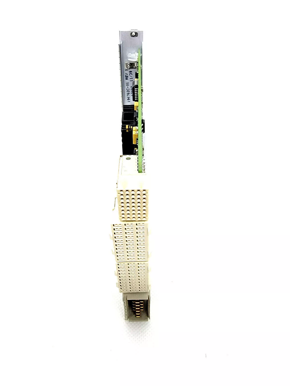
尺寸PXI Express模块尺寸(3U,单槽)
重量约200 g
三、应用场景
分布式自动化测试
汽车电子测试:在整车环境下远程控制多个PXI Express机箱,同步采集ECU信号、传感器数据与摄像头视频流。
航空航天测试:在风洞或飞行试验中,通过光纤连接远程测试设备,避免电磁干扰与信号衰减。
半导体测试:在洁净室内远程控制探针台与测试仪器,减少人员干预,提高测试一致性。
大规模数据采集
结构健康监测:在桥梁、建筑等大型结构中部署多个PXI Express机箱,通过光纤汇总振动、应变等传感器数据至中央服务器。
能源监测:在风电场或光伏电站中,远程采集逆变器、发电机等设备的电气参数,实现实时监控与故障诊断。
科研与国防
雷达与电子战:在野外测试场中,通过光纤连接远程雷达前端与控制中心,实现高带宽信号传输与实时分析。
量子计算:在低温实验室中,远程控制稀释制冷机内的量子比特控制模块,避免热噪声干扰。
四、软件支持
NI-DAQmx:支持通过光纤链路远程配置与控制数据采集卡(如NI PXIe-6368)。
NI TestStand:构建分布式测试序列,协调多个远程机箱的执行流程。
NI LabVIEW:通过TCP/IP或NI-XNET协议与PXIe-8370通信,开发自定义远程控制应用。
NI System Configuration API:动态发现与管理远程PXI Express系统资源。
五、典型配置示例
基础远程测试系统
主控制器:NI PXIe-8880(Intel Xeon八核控制器)
远程机箱:NI PXIe-1085(18槽PXI Express机箱)
连接模块:主控制器侧安装NI PXIe-8370,远程机箱侧安装NI PXIe-8370
光纤:OM4多模光纤(100米)
应用:汽车ECU硬件在环(HIL)测试。
1.Core Features
High-speed fiber-optic communication
Bandwidth:supports 40 Gbps full-duplex data transmission(20 Gbps in each direction),meeting the needs of large-scale real-time data transmission.
Latency:Typical round-trip delay<1μs,ensuring that remote control response speed is close to local operation.
Distance:Supports up to 300 meters of multimode fiber connection(OM4 fiber),or 10 kilometers of single-mode fiber connection(OS2 fiber).
Seamless PXI Express integration
Compatibility:Fully compatible with the PXI Express standard,supporting seamless connection with chassis such as NI PXIe-1085 and PXIe-1082.
Trigger synchronization:Transmit PXI trigger signals through fiber optic links to achieve nanosecond synchronization between remote chassis and main controller(<10 ns jitter).
Clock synchronization:Supports IEEE 1588 time synchronization protocol to ensure multi-chassis time consistency(accuracy<100 ns).
Flexible system expansion
Cascading capability:supports multi-level cascading(such as main controller→PXIe-8370→another PXIe-8370)to build a distributed test network.
Hybrid topology:supports star,chain or tree topologies to meet the needs of different test scenarios.
Hot plug:supports plugging and unplugging during chassis operation to simplify system maintenance and upgrades.
High reliability design
Redundant power supply:supports dual power input to improve system availability.
Industrial temperature range:operating temperature 0°C to 55°C,storage temperature-40°C to 70°C,adapt to harsh environments.
ESD protection:complies with IEC 61000-4-2 standard to prevent electrostatic damage.
2.Technical specifications
Parameter Specifications
Interface type 1×QSFP+fiber interface(supports 40 Gbps full-duplex)
Fiber type Multimode fiber(OM4,up to 300 meters)
Single-mode fiber(OS2,up to 10 kilometers)
Bandwidth 20 Gbps per direction(full-duplex 40 Gbps)
Delay Round-trip delay<1μs(typical value)
Trigger synchronization PXI trigger bus transmitted via optical fiber,jitter<10 ns
Clock synchronization Supports IEEE 1588 PTP,accuracy<100 ns
Power requirement 12 V DC,power consumption<15 W
Dimensions PXI Express module size(3U,single slot)
Weight About 200 g
3.Application scenarios
Distributed automated testing
Automotive electronics testing:Remotely control multiple PXI Express chassis in a vehicle environment to synchronously collect ECU signals,sensor data,and camera video streams.
Aerospace testing:In wind tunnels or flight tests,remote test equipment is connected via optical fiber to avoid electromagnetic interference and signal attenuation.
Semiconductor testing:Remotely control probe stations and test instruments in clean rooms to reduce human intervention and improve test consistency.
Large-scale data acquisition
Structural health monitoring:Deploy multiple PXI Express chassis in large structures such as bridges and buildings,and aggregate sensor data such as vibration and strain to a central server via optical fiber.
Energy monitoring:In wind farms or photovoltaic power plants,remotely collect electrical parameters of equipment such as inverters and generators to achieve real-time monitoring and fault diagnosis.
Scientific research and defense
Radar and electronic warfare:In field test sites,remote radar front ends are connected to control centers via optical fiber to achieve high-bandwidth signal transmission and real-time analysis.
Quantum computing:In cryogenic laboratories,remotely control the quantum bit control module in the dilution refrigerator to avoid thermal noise interference.
IV.Software support
NI-DAQmx:Supports remote configuration and control of data acquisition cards(such as NI PXIe-6368)via optical fiber links.
NI TestStand:Build distributed test sequences and coordinate the execution flow of multiple remote chassis.
NI LabVIEW:Communicate with PXIe-8370 through TCP/IP or NI-XNET protocol to develop custom remote control applications.
NI System Configuration API:Dynamically discover and manage remote PXI Express system resources.
V.Typical Configuration Example
Basic Remote Test System
Main Controller:NI PXIe-8880(Intel Xeon 8-core controller)
Remote Chassis:NI PXIe-1085(18-slot PXI Express Chassis)
Connection Module:NI PXIe-8370 installed on the main controller side and NI PXIe-8370 installed on the remote chassis side
Fiber:OM4 multimode fiber(100 meters)
Application:Automotive ECU hardware-in-the-loop(HIL)testing.